CAVITATION AND BUBBLE DYNAMICS
by
Christopher Earls Brennen © Oxford University Press 1995
CHAPTER 5.
TRANSLATION OF BUBBLES
5.1 INTRODUCTION
This chapter will briefly review the issues and problems involved in
constructing the equations of motion for individual bubbles (or drops or
solid particles) moving through a fluid and will therefore focus on
the dynamics of relative motion rather than the dynamics of growth
and collapse. For convenience we shall use the generic name ``particle''
when any or all of bubbles, drops, and solid particles are being
considered. The analyses are implicitly confined to those circumstances
in which the interactions between neighboring particles are
negligible. In very dilute multiphase flows in which the particles
are very small compared with the global dimensions of the flow and are
very far apart compared with the particle size, it is often sufficient
to solve for the velocity and pressure, ui(xi ,t)
and p(xi ,t),
of the continuous suspending fluid while ignoring the particles or
disperse phase. Given this solution one could then solve an equation
of motion for the particle to determine its trajectory.
This chapter will focus on the
construction of such a particle or bubble equation of motion.
Interactions between particles or, more particularly,
bubble, are left for later.
The body of fluid mechanical literature on the subject of
flows around particles or bodies is very large indeed. Here we present
a summary that focuses on a spherical particle of radius, R, and
employs the following common notation.
The components of the translational velocity of the center of the
particle will be denoted by Vi(t).
The velocity that the fluid would have had at the
location of the particle center in the absence of
the particle will be denoted by Ui(t).
Note that such a concept is difficult to extend to the case of interactive
multiphase flows.
Finally, the velocity of the particle relative to the fluid is
denoted by Wi(t)=Vi -Ui.
Frequently the approach used to construct equations for
Vi(t)
(or Wi(t))
given Ui(xi ,t) is to
individually estimate all the fluid forces acting on the particle and
to equate the total fluid force, Fi, to
mpdVi /dt (where mp
is the particle mass, assumed constant).
These fluid forces may include forces due to buoyancy, added mass, drag,
etc.
In the absence of fluid acceleration (dUi /dt=0)
such an approach can be made unambigiously; however, in the presence of
fluid acceleration, this kind of heuristic approach can be misleading.
Hence we concentrate in the next few sections on a fundamental
fluid mechanical approach, which minimizes possible ambiguities.
The classical results for a spherical particle or bubble
are reviewed first.
The analysis is confined to a suspending fluid that is incompressible and
Newtonian so that the basic equations to be solved are the
continuity equation
 | ......(5.1)
|
and the Navier-Stokes equations
 | ......(5.2)
|
where ρ and ν are the density and
kinematic viscosity of the suspending fluid.
It is assumed that the only external force is that due to gravity, g.
Then the actual pressure is p′=p-ρgz where z is a
coordinate measured vertically upward.
Furthermore, in order to maintain clarity we confine attention
to rectilinear relative motion in a direction conveniently chosen
to be the x1 direction.
5.2 HIGH Re FLOWS AROUND A SPHERE
For steady flows about a sphere in which
dUi /dt=dVi /dt=dWi /dt=0,
it is convenient to use a coordinate system,
xi , fixed in the particle as well as polar coordinates
(r,θ) and velocities ur,uθ as
defined in Figure 5.1.
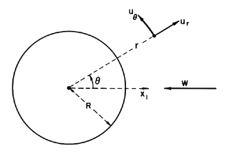
| Figure 5.1
Notation for a spherical particle.
|
Then Equations 5.1 and 5.2 become
 | ......(5.3)
|
and
 | ......(5.4)
|
 | ......(5.5)
|
The Stokes streamfunction, ψ, is defined
to satisfy continuity automatically:
 | ......(5.6)
|
and the inviscid potential flow solution is
 | ......(5.7)
|
 | ......(5.8)
|
 | ......(5.9)
|
 | ......(5.10)
|
where, because of the boundary condition
(ur)r=R=0, it follows that
D=-WR3/2.
In potential flow one may also define a velocity potential,
φ, such that ui=∂φ/∂xi.
The classic problem with such solutions is the fact
that the drag is zero, a circumstance termed D'Alembert's paradox.
The flow is symmetric about the x2 x3
plane through the origin and there is no wake.
The real viscous flows around a sphere at large Reynolds
numbers,
Re=2WR/ν>1, are well documented.
In the range from about 103 to 3×10⁵, laminar boundary layer
separation occurs at θ≈84°
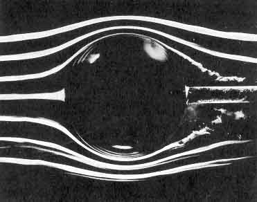
and a large wake is formed behind the sphere (see Figure 5.2).
Close to the sphere the ``near-wake'' is laminar;
further downstream transition and turbulence occurring in the
shear layers spreads to generate a turbulent ``far-wake.''
As the Reynolds number increases the shear layer transition moves
forward until, quite abruptly, the turbulent shear layer reattaches
to the body, resulting in a major change in the final position of
separation (θ≈120°) and in the form of the turbulent
wake (Figure 5.2).
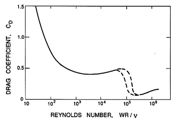
Associated with this change in flow pattern is a dramatic
decrease in the drag coefficient, CD (defined
as the drag force on the body in the negative
x1 direction divided by
½ρW2πR2),
from a value of about 0.5 in the laminar separation regime to
a value of about 0.2 in the turbulent separation regime
(Figure 5.3). At values of Re less than about
103 the flow becomes
quite unsteady with periodic shedding of vortices
from the sphere.
|
| 
|
Figure 5.2
Smoke visualization of the nominally
steady flows (from left to right) past a sphere showing, on the left,
laminar separation at Re=2.8×10⁵
and, on the right, turbulent
separation at Re=3.9×10⁵.
Photographs by F.N.M.Brown, reproduced
with the permission of the University of Notre Dame.
Figure 5.3
Drag coefficient on a sphere as a function of
Reynolds number. Dashed curves indicate the drag crisis regime in which the
drag is very sensitive to other factors such as the free stream turbulence.
5.3 LOW Re FLOWS AROUND A SPHERE
At the other end of the Reynolds number spectrum is the classic
Stokes solution for flow around a sphere.
In this limit the terms on the left-hand side of Equation
5.2 are neglected and the viscous term retained.
This solution has the form
 | ......(5.11)
|
 | ......(5.12)
|
 | ......(5.13)
|
where A and B are constants to be determined from
the boundary conditions on the surface of the sphere.
The force, F, on the ``particle" in the x1 direction is
 | ......(5.14)
|
Several subcases of this solution are of interest in the present context.
The first is the classic Stokes (1851) solution for a solid sphere
in which the no-slip boundary condition,
(uθ)r=R = 0, is applied
(in addition to the kinematic condition
(ur)r=R=0).
This set of boundary conditions, referred to
as the Stokes boundary conditions, leads to
 | ......(5.15)
|
The second case originates with Hadamard (1911)
and Rybczynski (1911) who suggested that, in the case of a bubble,
a condition of zero shear stress on the sphere surface
would be more appropriate than a condition of zero
tangential velocity, uθ. Then it transpires that
 | ......(5.16)
|
Real bubbles may conform to either the Stokes or
Hadamard-Rybczynski solutions depending
on the degree of contamination
of the bubble surface, as we shall discuss in more detail in the next
section. Finally, it is of interest to observe that the potential flow
solution given in Equations 5.7
to 5.10 is also a subcase with
 | ......(5.17)
|
However, another paradox, known as the
Whitehead paradox, arises
when the validity of these Stokes flow solutions at small
(rather than zero) Reynolds numbers is considered.
The nature of this paradox can be demonstrated by examining the
magnitude of the neglected term,
uj∂ui /∂xj, in the
Navier-Stokes equations relative to the magnitude of the retained term
ν∂2ui /∂xj∂xj.
As is evident from Equation 5.11, far from the sphere the
former is proportional to W2R/r2 whereas the latter
behaves like νWR/r3.
It follows that although the retained term will
dominate close to the body (provided the Reynolds number
Re=2WR/ν « 1), there will always be a radial position,
rc, given by R/rc=Re
beyond which the neglected term will exceed the retained
viscous term.
Hence, even if Re « 1, the Stokes solution is not
uniformly valid.
Recognizing this limitation, Oseen (1910) attempted to
correct the Stokes solution by retaining in
the basic equation an approximation to
uj∂ui /∂xj that would be
valid in the far field,
-W∂ui /∂x1.
Thus the Navier-Stokes equations are approximated by
 | ......(5.18)
|
Oseen was able to find a closed form solution to this
equation that satisfies the Stokes boundary conditions approximately:
 | ......(5.19)
|
which yields a drag force
 | ......(5.20)
|
It is readily shown that Equation 5.19
reduces to 5.11 as Re→0.
The corresponding solution for the Hadamard-Rybczynski boundary
conditions is not known to the author;
its validity would be more questionable since,
unlike the case of Stokes' boundary conditions,
the inertial terms
uj∂ui /∂xj
are not identically zero on the surface of the bubble.
More recently Proudman and Pearson (1957) and
Kaplun and Lagerstrom (1957) showed that Oseen's
solution is, in fact, the first term obtained when the method
of matched asymptotic expansions is used in an attempt to
patch together consistent asymptotic solutions of
the full Navier-Stokes equations for both the near field close
to the sphere and the far field.
They also obtained the next term in the expression for the drag force.
 | ......(5.21)
|
The additional term leads to an error of 1% at Re=0.3 and does
not, therefore, have much practical consequence.
The most notable feature of the Oseen solution is that the
geometry of the streamlines depends on the Reynolds number. The
downstream flow is not a mirror image of the upstream flow as in the
Stokes or potential flow solutions.
Indeed, closer examination of the Oseen solution reveals that,
downstream of the sphere, the streamlines are further apart and the
flow is slower than in the equivalent upstream location.
Furthermore, this effect increases with Reynolds number.
These features of the Oseen solution are entirely consistent
with experimental observations and represent
the initial development of a wake behind the body.
The flow past a sphere at Reynolds numbers between about 0.5
and several
thousand has proven intractable to analytical methods
though numerical solutions are numerous.
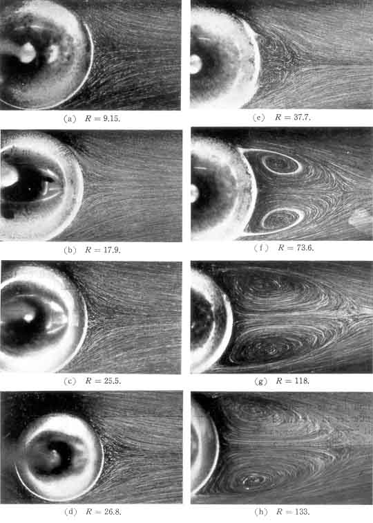
Experimentally, it is found that a recirculating zone (or vortex ring)
develops close to the rear stagnation point at about Re=30
(see Taneda 1956 and Figure 5.4).
With further increase in the Reynolds number this
recirculating zone or wake expands. Defining locations on the surface by
the angle from the front stagnation point, the separation point moves
forward from about 130° at Re=100 to about
115° at Re=300.
In the process the wake
reaches a diameter comparable to that of the sphere when
Re≈130. At this point
the flow becomes unstable and the ring vortex that makes up the wake
begins to oscillate (Taneda 1956). However, it continues to be attached to the
sphere until about Re=500 (Torobin and Gauvin 1959).
|
Figure 5.4
Streamlines of steady flow (from left to
right) past a sphere at various Reynolds numbers (from Taneda 1956,
reproduced by permission of the author).
At Reynolds numbers above about 500, vortices begin to be shed and
then convected downstream.
The frequency of vortex shedding has not been
studied as extensively as
in the case of a circular cylinder and seems to vary more with
Reynolds number. In terms of the conventional
Strouhal number, St, defined as
 | ......(5.22)
|
the vortex shedding frequencies, f, that Moller (1938) observed
correspond to a range of St varying from 0.3
at Re=1000 to about 1.8 at Re=5000.
Furthermore, as Re increases above 500 the flow
develops a
fairly steady ``near-wake'' behind which vortex shedding forms an
unsteady and increasingly turbulent ``far-wake.''
This process continues until, at a value of
Re of the order of 1000, the flow around the sphere and in the near-wake
again becomes quite steady. A recognizable boundary
layer has developed on the front of the sphere and separation settles
down to a position about 84° from the front stagnation point.
Transition to turbulence occurs on the free shear layer, which
defines the boundary of the near-wake and moves progessively forward
as the Reynolds number increases. The
flow is similar to that of the top picture in Figure 5.2.
Then the events described in the previous section occur with further
increase in the Reynolds number.
Since the Reynolds number range between 0.5 and several hundred
can often pertain in multiphase flows, one must resort to an empirical
formula for the drag force in this regime. A number of
empirical results are available; for example, Klyachko (1934)
recommends
 | ......(5.23)
|
which fits the data fairly well up to Re≈1000. At Re=1
the factor in the square brackets is 1.167,
whereas the same factor in Equation 5.20 is 1.187.
On the other hand, at Re=1000, the
two factors are respectively 17.7 and 188.5.
5.4 MARANGONI EFFECTS
As a postscript to the steady, viscous flows of the last section, it is
of interest to introduce and describe the forces that a bubble may
experience due to gradients in the
surface tension, S, over the
surface. These are called Marangoni effects. The gradients in
the surface tension can be caused by a number of different factors. For
example, gradients in the temperature, solvent concentration, or
electric potential can create gradients in the surface tension. The
``thermocapillary'' effects
due to temperature gradients have been
explored by a number of investigators (for example, Young, Goldstein, and
Block 1959) because of their importance in several technological
contexts. For most of the range of temperatures,
the surface tension decreases linearly with temperature, reaching
zero at the critical point. Consequently, the controlling
thermophysical property, dS/dT, is readily identified and more or less
constant for any given fluid. Some typical data for dS/dT is
presented in Table 5.1 and reveals a remarkably uniform value for this
quantity for a wide range of liquids.
| TABLE 5.1
|
|
Values of the temperature gradient of the surface tension, -dS/dT,
|
|
for pure liquid/vapor interfaces (in kg/s2°K).
|
|
|
|
Water | 2.02× 10⁻⁴ | Methane | 1.84× 10⁻⁴
|
|
Hydrogen | 1.59× 10⁻⁴ | Butane | 1.06× 10⁻⁴
|
|
Helium-4 | 1.02× 10⁻⁴ | Carbon Dioxide | 1.84× 10⁻⁴
|
|
Nitrogen | 1.92× 10⁻⁴ | Ammonia | 1.85× 10⁻⁴
|
|
Oxygen | 1.92× 10⁻⁴ | Toluene | 0.93× 10⁻⁴
|
|
Sodium | 0.90× 10⁻⁴ | Freon-12 | 1.18× 10⁻⁴
|
|
Mercury | 3.85× 10⁻⁴ | Uranium Dioxide | 1.11× 10⁻⁴
|
Surface tension gradients affect free surface flows because a gradient,
dS/ds, in a direction, s, tangential to a surface clearly requires
that a shear stress act in the negative s direction in order that the
surface be in equilibrium. Such a shear stress would then modify the
boundary conditions (for example, the Hadamard-Rybczynski conditions
used in the preceding section), thus altering the flow and the forces
acting on the bubble.
As an example of the Marangoni effect, we will examine the steady motion
of a spherical bubble in a viscous fluid when there exists a gradient
of the temperature (or other controlling physical property),
dT/dx1,
in the direction of motion (see Figure 5.1). We must first determine
whether the temperature (or other controlling property) is affected
by the flow. It is illustrative to consider two special cases from
a spectrum of possibilities. The first and simplest special case,
which is not so relevant to the thermocapillary phenomenon, is to
assume that T=(dT/dx1)x1 throughout the flow field so that, on the
surface of the bubble,
 | ......(5.24)
|
Much more realistic is the assumption that thermal conduction dominates
the heat transfer (Laplacian of T is zero) and that there is no
heat transfer through the surface of the bubble. Then it follows from
the solution of Laplace's equation for the conductive heat transfer
problem that
 | ......(5.25)
|
The latter is the solution presented by Young, Goldstein, and Block (1959),
but it differs from Equation 5.24 only in terms of the effective value
of dS/dT. Here we shall employ Equation 5.25 since we focus on
thermocapillarity, but other possibilities such as
Equation 5.24 should be borne in mind.
For simplicity we will continue to assume that the bubble remains spherical.
This assumption implies that the surface tension differences are small
compared with the absolute level of S and that the stresses normal to the
surface are entirely dominated by the surface tension.
With these assumptions the tangential stress boundary condition for the
spherical bubble becomes
 | ......(5.26)
|
and this should replace the Hadamard-Rybczynski condition of zero shear
stress that was used in the preceding section. Applying Equation
5.26 with Equation 5.25 and the usual kinematic condition,
(ur)r=R=0, to the
general solution of the preceding section leads to
 | ......(5.27)
|
and consequently, from Equation 5.14,
the force acting on the bubble becomes
 | ......(5.28)
|
In addition to the normal Hadamard-Rybczynski drag (first term), we can
identify a Marangoni force, 2πR2(dS/dx1),
acting on the
bubble in the direction of decreasing surface tension. Thus, for
example, the presence of a uniform temperature gradient,
dT/dx1,
would lead to an additional force on the bubble of magnitude
2πR2(-dS/dT)(dT/dx1)
in the direction of the warmer fluid since
the surface tension decreases with temperature. Such thermocapillary
effects have been observed and measured by
Young, Goldstein, and Block (1959) and others.
Finally, we should comment on a related effect caused by surface
contaminants that increase the surface
tension. When a bubble is moving
through liquid under the action, say, of gravity, convection may cause
contaminants to accumulate on the downstream side of the bubble. This
will create a positive dS/dθ gradient which, in turn, will generate
an effective shear stress acting in a direction opposite to the flow.
Consequently, the contaminants tend to immobilize the surface.
This will cause the
flow and the drag to change from the Hadamard-Rybczynski solution to the
Stokes solution for zero tangential velocity. The effect is more
pronounced for smaller bubbles since, for a given surface tension
difference, the Marangoni force becomes larger relative to the
buoyancy force as the bubble size decreases. Experimentally, this means
that surface contamination usually results in Stokes drag
for spherical bubbles smaller than a certain size and in
Hadamard-Rybczynski drag for spherical bubbles larger than that size.
Such a transition is observed in experiments measuring the rise velocity
of bubbles as, for example, in the Haberman and Morton (1953)
experiments discussed in more detail in Section 5.12.
The effect has
been analyzed in the more complex hydrodynamic case at higher Reynolds
numbers by Harper, Moore, and Pearson (1967).
5.5 MOLECULAR EFFECTS
Though only rarely important in the context of bubbles, there
are some effects that can be caused by the molecular motions in the
surrounding fluid. We briefly list some of these here.
When the mean free path of the molecules in the surrounding fluid,
λ, becomes comparable with the size of the particles, the
flow will clearly deviate from the continuum models, which are only
relevant when λ « R. The Knudsen number,
Kn=λ/2R,
is used to characterize these circumstances, and Cunningham (1910)
showed that the first-order correction for small but finite Knudsen
number leads to an additional factor, (1+2AKn), in the Stokes drag
for a spherical particle. The numerical factor, A, is roughly a constant
of order unity (see, for example, Green and Lane 1964).
When the
impulse generated by the collision of a single fluid molecule with the
particle is large enough to cause significant change in the particle
velocity, the resulting random motions of the particle are called
``Brownian motion'' (Einstein 1956).
This leads to diffusion of solid
particles suspended in a fluid. Einstein showed that the diffusivity, D,
of this process is given by
 | ......(5.29)
|
where k is Boltzmann's constant. It follows
that the typical rms displacement, λ, of the particle in a
time, t, is given by
 | ......(5.30)
|
Brownian motion is usually only significant for micron- and
sub-micron-sized particles.
The example quoted by Einstein is that of a 1μm diameter particle
in water at 17°C for which the typical displacement during one
second is 0.8μm.
A third, related phenomenon is the reponse of a particle to the
collisions of molecules when there is a significant temperature
gradient in the fluid. Then the impulses imparted to the particle
by molecular collisions on the hot side of the particle will be
larger than the impulses on the cold side. The particle will therefore
experience a net force driving it in the direction of the colder fluid.
This phenomenon is known as thermophoresis
(see, for example, Davies 1966). A similar phenomenon known as
photophoresis occurs
when a particle is subjected to nonuniform radiation. One could, of
course, include in this list the Bjerknes forces
described in Section 4.10 since they
constitute sonophoresis.
5.6 UNSTEADY PARTICLE MOTIONS
Having reviewed the steady motion of a particle relative to
a fluid, we must now consider the consequences of unsteady relative
motion in which either the particle or the fluid or both are accelerating.
The complexities of fluid acceleration are delayed until the
next section.
First we shall consider the simpler circumstance in which
the fluid is either at rest or has a steady uniform streaming motion
(U=constant) far from the particle.
Clearly the second case is readily reduced to the first by a simple
Galilean transformation and it will be assumed that this has been
accomplished.
In the ideal case of unsteady inviscid potential flow, it can then
be shown by using the concept of the total kinetic energy of the fluid
that the force on a rigid particle in an incompressible flow is given by
Fi, where
 | ......(5.31)
|
where Mij is called the added mass matrix
(or tensor) though the
name ``induced inertia tensor'' used by Batchelor
(1967) is, perhaps,
more descriptive. The reader is referred to Sarpkaya and Isaacson (1981),
Yih (1969), or Batchelor (1967) for detailed descriptions of such analyses.
The above mentioned methods also show that Mij for any
finite particle can be obtained from knowledge of several steady
potential flows. In fact,
 | ......(5.32)
|
where the integration is performed over the entire volume of the fluid.
The velocity field, uij, is the fluid velocity in the
i direction caused by the steady
translation of the particle with unit velocity in the j direction.
Note that this means that Mij is necessarily a symmetric matrix.
Furthermore, it is clear that particles with planes of symmetry will
not experience a force perpendicular to that plane when the
direction of acceleration is parallel to that plane.
Hence if there is a plane of symmetry perpendicular to the k
direction, then for i≠k, Mki=Mik=0,
and the only off-diagonal matrix elements that can be nonzero are
Mij, j≠k, i≠k.
In the special case of the sphere all
the off-diagonal terms will be zero.
Tables of some available values of the diagonal
components of Mij are given by Sarpkaya and Isaacson (1981)
who also summarize the experimental results, particularly for planar flows
past cylinders. Other compilations of added mass results can be found
in Kennard (1967), Patton (1965), and Brennen (1982).
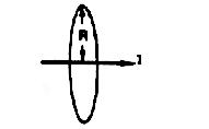
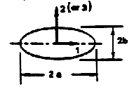
Some typical values for three-dimensional particles are listed in
Table 5.2.
The uniform diagonal value for a sphere (often referred to simply as
the added mass of a sphere) is 2ρπR3/3 or one-half
the displaced mass of fluid.
This value can readily be obtained from Equation 5.32 using
the steady flow results given in Equations 5.7 to 5.10.
In general, of course, there is no
special relation between the added mass and the displaced mass.
Consider, for example, the case of the infinitely thin plate or
disc with zero displaced mass which has a finite added mass in the
direction normal to the surface. Finally, it should be noted that the
literature contains little, if any, information on off-diagonal components
of added mass matrices.
| TABLE 5.2
|
|
Added masses (diagonal terms in Mij) for some
three-dimensional bodies (particles):
|
|
(T) Potential flow calculations, (E) Experimental data from Patton (1965).
|
|
|
| Particle | | Matrix Element | Value
|
|
|
| Sphere (T)
| 
| Mii | 2ρπR3/3
|
| Disc (T)
| 
| M11 | 8ρR3/3
|
| Ellipsoids (T)
| 
| Mii=Kii4ρπab2/3
|
| a/b | K11 | K22(K33)
| | 2 | 0.209 | 0.702
| | 5 | 0.059 | 0.895
| | 10 | 0.021 | 0.960
|
|
| Sphere near
| | Plane
| | Wall (T)
|
| 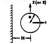
| Mii= Kii 4ρπR3/3
|
| K11=½(1+3R3/8H3+....)
| | K22=½(1+3R3/16H3+....)
| | K33=K22
|
|
| Sphere near
| | Free
| | Surface (E)
|
| 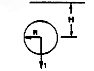
| Mii= Kii 4ρπR3/3
|
| H/R | K11
| | 8.0 | 0.52
| | 4.0 | 0.59
| | 2.0 | 0.54
| | 1.0 | 0.44
| | 0.0 | 0.25
|
|
Now consider the application of these potential
flow results to real viscous flows at high Reynolds numbers
(the case of low Reynolds number flows will be discussed in
Section 5.8).
Significant doubts about the applicability of the added masses calculated
from potential flow analysis would be justified because of the experience
of D'Alembert's paradox for steady potential flows and the substantial
difference between the streamlines of the potential and actual flows.
Furthermore, analyses of experimental results will require
the separation of the ``added mass'' forces from the viscous drag forces.
Usually this is accomplished by heuristic summation of the
two forces so that
 | ......(5.33)
|
where Cij is a lift and drag coefficient matrix and A
is a typical cross-sectional area for the body.
This is known as Morison's equation
(see Morison et al. 1950).
Actual unsteady high Reynolds number flows are more complicated and
not necessarily compatible with such simple superposition.
This is reflected in the fact that the coefficients, Mij and
Cij, appear from the experimental results to be not only
functions of Re but also functions of the reduced time
or frequency of the unsteady motion.
Typically experiments involve either oscillation of a body in a fluid
or acceleration from rest.
The most extensively studied case involves planar flow past a cylinder
(for example, Keulegan and Carpenter 1958),
and a detailed review of this data is included in Sarkaya and
Isaacson (1981).
For oscillatory motion of the cylinder with velocity amplitude,
UM , and period, t*, the coefficients are
functions of both the Reynolds number, Re=2UMR/ν, and
the reduced period or
Keulegan-Carpenter number,
Kc=UM t*/2R.
When the amplitude, UM t*, is less than about
10R (Kc<5), the inertial effects dominate and
Mii
is only a little less than its potential flow value
over a wide range of Reynolds numbers
(104<Re<106).
However, for larger values of Kc, Mii can be substantially
smaller than this and, in some range of Re and Kc, may
actually be negative.
The values of Cii (the drag coefficient) that are deduced
from experiments are also a complicated function of Re and Kc.
The behavior of the coefficients is particularly
pathological when the reduced period,
Kc, is close to that of vortex shedding
(Kc of the order of 10). Large transverse or ``lift'' forces can be
generated under these circumstances.
To the author's knowledge, detailed investigations of this kind
have not been made for a spherical body, but one might expect the
same qualitative phenomena to occur.
5.7 UNSTEADY POTENTIAL FLOW
In general, a particle moving in any flow other than a steady
uniform stream will experience fluid accelerations, and it is
therefore necessary to consider the structure of the
equation governing the particle motion under these circumstances.
Of course, this will include the special case of acceleration of a
particle in a fluid at rest (or with a steady streaming motion).
As in the earlier sections we shall confine the detailed solutions to
those for a spherical particle or bubble.
Furthermore, we consider only those circumstances in which both the
particle and fluid acceleration are in one
direction, chosen for convenience to be the x1 direction.
The effect of an external force field such as gravity will be
omitted; it can readily be inserted into any of the solutions that follow
by the addition of the conventional buoyancy force.
All the solutions discussed are obtained in an accelerating frame of
reference fixed in the center of the fluid particle.
Therefore, if the velocity of the particle in some original, noninertial
coordinate system, xi*, was V(t) in the
x1* direction, the Navier-Stokes equations in
the new frame, xi, fixed in the particle center are
 | ......(5.34)
|
where the pseudo-pressure, P, is related to the actual pressure,
p, by
 | ......(5.35)
|
Here the conventional time derivative of V(t) is
denoted by d/dt, but it should be noted that in the original
xi* frame it implies a Lagrangian derivative
following the particle.
As before, the fluid is assumed incompressible (so that continuity
requires ∂ui /∂xi=0) and Newtonian.
The velocity that the fluid would have at the xi origin in the
absence of the particle is then W(t) in the
x1 direction.
It is also convenient to define the quantities r, θ,
ur,
uθ as shown in Figure 5.1 and the Stokes
streamfunction as in Equations 5.6.
In some cases we shall also be able to consider the unsteady
effects due to growth of the bubble so the radius is denoted
by R(t).
First consider inviscid potential flow for which Equations 5.34
may be integrated to obtain the Bernoulli equation
 | ......(5.36)
|
where φ is a velocity potential
(ui=∂φ/∂xi) and ψ
must satisfy the equation
 | ......(5.37)
|
This is of course the same equation as in steady flow and has
harmonic solutions, only five of which are necessary
for present purposes:
 | ......(5.38)
|
 | ......(5.39)
|
 | ......(5.40)
|
 | ......(5.41)
|
The first part, which involves W and D, is identical
to that for steady translation.
The second, involving A and B,
will provide the fluid velocity gradient
in the x1 direction, and the third, involving E,
permits a time-dependent particle (bubble) radius.
The W and A terms
represent the fluid flow in the absence of the particle, and
the D, B ,and E terms allow the boundary condition
 | ......(5.42)
|
to be satisfied provided
 | ......(5.43)
|
In the absence of the particle the velocity of the fluid at
the origin, r=0, is simply -W in the x1
direction and the gradient of the velocity
∂u1/∂x1=4A/3.
Hence A is determined from the fluid velocity gradient in the
original frame as
 | ......(5.44)
|
Now the force, F1, on the bubble in the x1 direction
is given by
 | ......(5.45)
|
which upon using Equations 5.35, 5.36,
and 5.39 to 5.41
can be integrated to yield
 | ......(5.46)
|
Reverting to the original coordinate system and using τ
as the sphere volume for convenience (τ=4πR3/3),
one obtains
 | ......(5.47)
|
where the two Lagrangian time derivatives are defined by
 | ......(5.48)
|
 | ......(5.49)
|
Equation 5.47 is an important result, and care must be taken not
to confuse the different time derivatives contained in it. Note that
in the absence of bubble growth, of viscous drag, and of body forces,
the equation of motion that results from setting
F1=mp dV/dt* is
 | ......(5.50)
|
where mp is the mass of the ``particle.'' Thus for a massless bubble
the acceleration of the bubble is three times the fluid acceleration.
In a more comprehensive study of unsteady potential flows
Symington (1978) has shown that the result for more
general (i.e., noncolinear) accelerations of the fluid and particle
is merely the vector equivalent of Equation 5.47:
 | ......(5.51)
|
where
 | ......(5.52)
|
The first term in Equation 5.51 represents the
conventional added mass effect due to the particle acceleration.
The factor 3/2 in the second term due to the fluid acceleration
may initially seem surprising. However, it is made up of two components:
- ½ρτdVi /dt*, which is the
added mass effect of the fluid acceleration
- ρτDUi /Dt*,
which is a ``buoyancy''-like force due to the pressure gradient
associated with the fluid acceleration.
The last term in Equation 5.51
is caused by particle (bubble) volumetric growth,
dτ/dt*, and is similar in form to the force on a
source in a uniform stream.
Now it is necessary to ask how this force given by Equation 5.51
should be used in the practical construction of an equation
of motion for a particle.
Frequently, a viscous drag force FiD, is quite
arbitrarily added to Fi to obtain some total ``effective"
force on the particle.
Drag forces, FiD, with the conventional forms
 | ......(5.53)
|
 | ......(5.54)
|
have both been employed in the literature.
It is, however, important to recognize that there is no fundamental
analytical justification for such superposition of these forces.
At high Reynolds numbers, we noted in the last section that
experimentally observed added masses are indeed quite close
to those predicted by potential flow within certain parametric
regimes, and hence the superposition has some experimental justification.
At low Reynolds numbers, it is improper to use the results of the
potential flow analysis. The appropriate analysis under these circumstances
is examined in the next section.
5.8 UNSTEADY STOKES FLOW
In order to elucidate some of the issues raised in the last
section, it is instructive to examine solutions for the
unsteady flow past a sphere in low Reynolds number Stokes flow.
In the asymptotic case of zero Reynolds number, the solution of
Section 5.3
is unchanged by unsteadiness, and
hence the solution at any instant in time
is identical to the steady-flow solution for the same particle velocity.
In other words, since the fluid has no inertia, it is always in static
equilibrium.
Thus the instantaneous force is identical to that for the steady
flow with the same Vi(t).
The next step is therefore to investigate the effects of small but nonzero
inertial contributions.
The Oseen solution provides some indication of the effect of the
convective inertial terms,
uj∂ui /∂xj,
in steady flow. Here we investigate the effects of the
unsteady inertial term, ∂ui /∂t.
Ideally it would be best to include both the
∂ui /∂t term and the Oseen approximation
to the convective term, U∂ui /∂x.
However, the resulting unsteady
Oseen flow is sufficiently difficult that only small-time expansions
for the impulsively started motions of droplets and bubbles exist
in the literature (Pearcey and Hill 1956).
Consider, therefore the unsteady Stokes equations in the absence
of the convective inertial terms:
 | ......(5.55)
|
Since both the equations and the boundary conditions used below
are linear in ui, we need only consider colinear particle and fluid
velocities in one direction, say x1.
The solution to the general case of noncolinear
particle and fluid velocities and accelerations may then
be obtained by superposition.
As in Section 5.7 the colinear problem is solved by first
transforming to an accelerating coordinate frame,
xi, fixed in the center of the particle so that
P=p+ρx1dV/dt.
Elimination of P by taking the curl of Equation 5.55 leads to
 | ......(5.56)
|
where L is the same operator as defined in Equation 5.37.
Guided by both the steady Stokes flow and the unsteady potential
flow solution, one can anticipate a solution of the form
 | ......(5.57)
|
plus other spherical harmonic functions.
The first term has the form of the steady
Stokes flow solution; the last term would be required if the
particle were a growing spherical bubble.
After substituting Equation 5.57 into Equation 5.56,
the equations for f, g, h are
 | ......(5.58)
|
 | ......(5.59)
|
 | ......(5.60)
|
Moreover, the form of the expression for the force,
F1, on the spherical particle
(or bubble) obtained by evaluating the stresses on the
surface and integrating is
 | ......(5.61)
|
It transpires that this is independent of g or h.
Hence only the solution to Equation 5.58 for
f(r,t) need be sought in order to find the force on a spherical particle,
and the other spherical harmonics that might have been included in
Equation 5.58 are now seen to be unnecessary.
Fourier or Laplace transform methods may be used to solve
Equation 5.58 for f(r,t), and we choose Laplace transforms.
The Laplace transforms for the relative velocity W(t),
and the function f(r,t) are denoted by
 (s)
and
 (r,s):
 | ......(5.62)
|
Then Equation 5.58 becomes
 | ......(5.63)
|
where α2=s/ν, and the solution after application
of the condition that
 1(s,t)
far from the particle be equal to
 (s) is
 | ......(5.64)
|
where α=(s/ν)½ and A and B
are as yet undetermined functions of s.
Their determination requires application of
the boundary conditions on r=R. In terms of A and B the
Laplace transform of the force
 1(s) is
 | ......(5.65)
|
where
 | ......(5.66)
|
The classical solution (see Landau and Lifshitz 1959)
is for a solid sphere (i.e., constant R) using
the no-slip (Stokes) boundary condition for which
 | ......(5.67)
|
and hence
 | ......(5.68)
|
so that
 | ......(5.69)
|
For a motion starting at rest at t=0 the
inverse Laplace transform of this yields
 | ......(5.70)
|
where
 is a dummy time variable.
This result must then be written in the original
coordinate framework with W=V-U and
can be generalized to the noncolinear case by
superposition so that
 | ......(5.71)
|
where d/dt* is the Lagrangian time derivative
following the particle. This is then the general force on the particle
or bubble in unsteady Stokes flow when the Stokes boundary conditions
are applied.
Compare this result with that obtained from the
potential flow analysis, Equation 5.51
with τ taken as constant.
It is striking to observe that the coefficients of the added mass
terms involving dVi /dt* and
dUi /dt* are identical to those of the
potential flow solution.
On superficial examination it might be noted that
dUi /dt* appears in Equation 5.71 whereas
DUi /Dt* appears in 5.51; the difference
is, however, of order
Wj∂Ui /dxj and terms
of this order have already been
dropped from the equation of motion on the basis that
they were negligible compared with the temporal derivatives
like ∂Wi /∂t.
Hence it is inconsistent with the initial assumption to
distinguish between d/dt* and
D/Dt* in the present unsteady Stokes flow solution.
The term 9νW/2R2 in Equation 5.71 is, of course, the
steady Stokes drag. The new phenomenon introduced by this analysis is
contained in the last term of Equation 5.71.
This is a fading memory term that is often named the
Basset term after one of its identifiers (Basset 1888).
It results from the fact that additional vorticity created at the solid particle
surface due to relative acceleration diffuses into the flow and creates
a temporary perturbation in the flow field.
Like all diffusive effects it produces an ω½
term in
the equation for oscillatory motion.
Before we conclude this section, comment should be included on
two other analytical results.
Morrison and Stewart (1976) have considered the case of a spherical bubble
for which the Hadamard-Rybczynski
boundary conditions
rather than the Stokes conditions are applied.
Then, instead of the conditions of Equation 5.67,
the conditions for zero normal
velocity and zero shear stress on the surface require that
 | ......(5.72)
|
and hence in this case (see Morrison and Stewart 1976)
 | ......(5.73)
|
so that
 | ......(5.74)
|
The inverse Laplace transform of this for motion starting
at rest at t=0 is
 | ......(5.75)
|
Comparing this with the
solution for the Stokes conditions, we note that the
first two terms are unchanged and
the third term is the expected Hadamard-Rybczynski steady drag term
(see Equation 5.16).
The last term is significantly different from the Basset
term in Equation 5.71 but still represents a receding memory.
The second interesting case is that for unsteady Oseen
flow, which
essentially consists of attempting to solve the Navier-Stokes
equations with the convective initial terms approximated by
Uj∂ui /∂xj.
Pearcey and Hill (1956) have examined the small-time behavior of
droplets and bubbles started from rest when this term is included
in the equations.
5.9 GROWING OR COLLAPSING BUBBLES
We now return to the discussion of higher Re flow and specifically
address the effects due to bubble growth or collapse.
A bubble that grows or collapses close to a boundary may undergo
translation due to the asymmetry induced by that boundary. A relatively
simple example of the analysis of this class of flows is the case
of the growth or collapse of a spherical bubble near a
plane boundary, a problem first solved by Herring (1941)
(see also Davies and Taylor 1942, 1943). Assuming that the only translational
motion of the bubble (with velocity, W)
is perpendicular to the plane boundary,
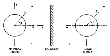
the geometry of the bubble and its image in the boundary will be as
shown in Figure 5.5. For convenience, we define additional polar
cooordinates,
( ,
,
 ),
with origin at the center
of the image bubble. Assuming inviscid, irrotational flow,
Herring (1941) and Davies and Taylor (1943) constructed
the velocity potential, φ, near the bubble by considering an expansion
in terms of R/h where h is the distance of the bubble center from the
boundary. Neglecting all terms that are of order
R3/h3 or higher,
the velocity potential can be obtained by superposing the individual
contributions from the bubble source/sink, the image source/sink, the
bubble translation dipole, the image dipole, and one correction factor
described below. This combination yields
 | ......(5.76)
|
The first and third terms are the source/sink contributions from the
bubble and the image respectively. The second and fourth terms are the
dipole contributions due to the translation of the bubble and the image.
The last term arises because the source/sink in the bubble needs to be
displaced from the bubble center by an amount
R3/8h2 normal to the
wall in order to satisfy the boundary condition on the surface
of the bubble to order R2/h2. All other terms of
order R3/h3 or higher are neglected in this analysis assuming that
the bubble is sufficiently far from the boundary so that h » R.
Finally, the sign choice on the last three
terms of Equation 5.76 is as follows: the upper, positive sign
pertains to the case of a solid boundary and the lower, negative sign
provides an approximate solution for a free surface boundary.
Figure 5.5
Schematic of a bubble undergoing growth or collapse
close to a plane boundary. The associated translational velocity is denoted
by W.
It remains to use this solution to determine the translational motion,
W(t), normal to the boundary. This is accomplished by invoking the
condition that there
is no net force on the bubble. Using the unsteady Bernoulli equation and
the velocity potential and fluid velocities obtained from Equation 5.76,
Davies and Taylor (1943) evaluate the pressure at the bubble
surface and thereby obtain an expression for the force, Fx,
on the bubble in the x direction:
 | ......(5.77)
|
Adding the effect of buoyancy due to a component, gx, of the gravitational
acceleration in the x direction, Davies and Taylor then
set the total force equal to zero and
obtain the following equation of motion for W(t):
 | ......(5.78)
|
In the absence of gravity this corresponds to the equation of motion
first obtained by Herring (1941).
Many of the studies of growing and collapsing bubbles near boundaries
have been carried out in the context of underwater
explosions (see Cole 1948). An example
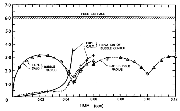
illustrating the solution of Equation 5.78 and the comparison
with experimental data is included in Figure 5.6 taken from
Davies and Taylor (1943).
Figure 5.6
Data from Davies and Taylor (1943) on the mean radius and central
elevation of a bubble in oil generated by a spark-initiated explosion of
1.32×10⁶ergs situated 6.05cm below the free surface.
The two measures of the bubble radius are one half of the horizontal span
(triangles) and one quarter of the sum of the horizontal and
vertical spans (circles). Theoretical calculations using Equation
5.78 indicated by the solid lines.
Another application of this analysis is to the translation of cavitation
bubbles near walls. Here the motivation is to understand the development
of impulsive loads on the solid surface
(see Section 3.6), and
therefore the primary focus is on bubbles close to the wall so that
the solution described above is of limited value since it
requires h » R.
However, as discussed in Section 3.5,
considerable progress has been
made in recent years in developing analytical methods for the
solution of the inviscid free surface flows of bubbles near boundaries.
One of the concepts that is particularly useful in determining the
direction of bubble translation is based on a
property of the flow first introduced by Kelvin (see Lamb 1932) and called
the Kelvin impulse. This vector property applies
to the flow generated by a finite particle or bubble in a fluid; it is
denoted by IKi and defined by
 | ......(5.79)
|
where φ is the velocity potential of the irrotational flow,
SB
is the surface of the bubble, and ni is the outward normal at that
surface (defined as positive into the bubble).
If one visualizes a bubble in a fluid at rest, then the Kelvin impulse
is the impulse that would have to be applied to the bubble in order
to generate the motions of the fluid related to the bubble motion.
Benjamin and Ellis (1966) were the first to
demonstrate the value of this property in determining the interaction
between a growing or collapsing bubble and a nearby boundary (see also
Blake and Gibson 1987).
5.10 EQUATION OF MOTION
In a multiphase flow with a very dilute discrete phase
the fluid forces discussed in Sections 5.1 to 5.8
will determine the motion of the particles that constitute that
discrete phase. In this section we discuss the implications of some
of the fluid force terms. The equation that determines the particle velocity,
Vi, is generated by equating the total force,
FiT, on the particle to
mpdVi /dt*.
Consider the motion of a spherical particle or (bubble) of mass
mp and volume τ (radius R)
in a uniformly accelerating fluid.
The simplest example of this is the vertical motion of a particle
under gravity, g, in a pool of otherwise quiescent fluid.
Thus the results will be written in terms of the buoyancy force.
However, the same results apply to motion generated by any
uniform acceleration of the fluid, and hence g
can be interpreted as a general uniform fluid acceleration
(dU/dt).
This will also allow some tentative conclusions to be drawn
concerning the relative motion of a particle in the
nonuniformly accelerating fluid situations that can
occur in general multiphase flow.
For the motion of a sphere at small relative Reynolds number,
ReW « 1 (where ReW=2WR/ν and
W is the typical magnitude of the relative velocity), only the
forces due to buoyancy and the weight of the particle need
be added to Fi as given by Equations 5.71 or 5.75
in order to obtain FiT.
This addition is simply given by
(ρτ-mp)gi where g is a vector
in the vertically upward direction with magnitude equal to the acceleration
due to gravity.
On the other hand, at high relative Reynolds numbers,
ReW » 1,
one must resort to a more heuristic approach in which the fluid forces
given by Equation 5.51 are supplemented by drag (and lift)
forces given by
½ρACij|Wj|Wj
as in Equation 5.33.
In either case it is useful to nondimensionalize the resulting equation
of motion so that the pertinent nondimensional parameters can be
identified.
Examine first the case in which the relative velocity,
W (defined as positive in the direction of the
acceleration, g, and therefore positive in the vertically upward
direction of the rising bubble or sedimenting particle), is sufficiently
small so that the
relative Reynolds number is much less than unity.
Then, using the Stokes boundary conditions,
the equation governing
W may be obtained from Equation 5.70 as
 | ......(5.80)
|
where the dimensionless time
 | ......(5.81)
|
and w=W/W∞ where
W∞ is the steady
terminal velocity given by
 | ......(5.82)
|
In the absence of the Basset term the solution of Equation 5.80
is simply
 | ......(5.83)
|
and the typical response time, tr, is called the relaxation
time for particle velocity (see, for example,
Rudinger 1969). In the general case that includes the Basset
term the dimensionless solution, w(t*),
of Equation 5.80 depends only on the parameter
mp/ρτ
(particle mass/displaced fluid mass) appearing in the Basset term.
Indeed, the dimensionless Equation 5.80 clearly illustrates
the fact that the Basset term is much less important for solid particles
in a gas where mp/ρτ » 1 than it is for bubbles
in a liquid
where mp/ρτ « 1. Note also that for initial
conditions of zero
relative velocity (w(0)=0) the small-time solution of Equation 5.80
takes the form
 | ......(5.84)
|
Hence the initial acceleration at t=0 is given
dimensionally by
2g(1-mp/ρτ)/(1+2mp/ρτ)
or 2g in the case of a massless bubble
and -g in the case of a heavy solid particle in a gas where
mp » ρτ. Note also that the effect
of the Basset term is to reduce the acceleration of the
relative motion, thus increasing the time required to achieve
terminal velocity.
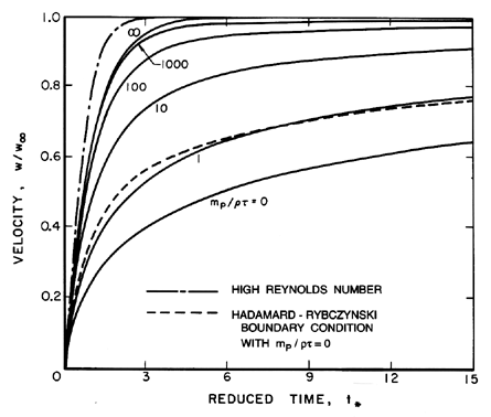
Numerical solutions of the form of w(t*)
for various mp/ρτ are shown in
Figure 5.7 where the delay caused by the Basset term can be clearly
seen. In fact in the later stages of approach to the terminal
velocity the Basset term dominates over the added mass term,
(dw/dt*). The integral in the Basset term becomes
approximately 2t*½dw/dt*
so that the final approach to w=1 can be approximated by
 | ......(5.85)
|
where C is a constant. As can be seen in Figure 5.7, the result is
a much slower approach to W∞ for small
mp/ρτ
than for larger values of this quantity.
Figure 5.7
The velocity, W, of a particle released
from rest at t*=0 in a quiescent fluid and its approach to terminal
velocity, W∞. Horizontal axis is a dimensionless time
defined in text. Solid lines represent the low Reynolds number
solutions for various particle mass/displaced mass ratios,
mp/ρτ, and the Stokes boundary condition. The dashed line is for
the Hadamard-Rybczynski boundary condition and
mp/ρτ=0. The
dash-dot line is the high Reynolds number result; note that
t* is nondimensionalized differently in that case.
The case of a bubble with Hadamard-Rybczynski
boundary conditions is very similar except that
 | ......(5.86)
|
and the equation for w(t*) is
 | ......(5.87)
|
where the function, Γ(ξ), is given by
 | ......(5.88)
|
For the purposes of comparison the form of
w(t*) for the Hadamard-Rybczynski boundary condition with
mp/ρτ=0 is also shown in
Figure 5.7. Though the altered Basset term leads to a more rapid
approach to terminal velocity than occurs for the Stokes boundary
condition, the difference is not qualitatively significant.
If the terminal Reynolds number is much greater than
unity then, in the absence of particle growth, Equation
5.51 heuristically supplemented with a
drag force of the form of Equation 5.53 leads to the following
equation of motion for unidirectional motion:
 | ......(5.89)
|
where w=W/W∞,t*=t/tr,
 | ......(5.90)
|
and
 | ......(5.91)
|
The solution to Equation 5.89 for w(0)=0,
 | ......(5.92)
|
is also shown in Figure 5.7 though, of course, t* has a
different definition in this case.
For the purposes of reference in Section 5.12 note that,
if we define
a Reynolds number, Re, Froude number,
Fr, and drag coefficient, CD, by
 | ......(5.93)
|
then the expressions for the terminal velocities, W∞,
given by Equations 5.82, 5.86, and 5.91 can be
written as
 | ......(5.94)
|
respectively. Indeed, dimensional analysis of the governing
Navier-Stokes equations requires that the general
expression for the terminal velocity can be written as
 | ......(5.95)
|
or, alternatively, if CD is defined as
4/3Fr2, then
it could be written as
 | ......(5.96)
|
5.11 MAGNITUDE OF RELATIVE MOTION
Qualitative estimates of the magnitude of the
relative motion in multiphase flows can be
made from the analyses of the last section.
Consider a general steady fluid flow characterized
by a velocity, U, and a typical dimension,
ℓ; it may, for example, be useful to visualize the
flow in a converging nozzle of length,
ℓ, and mean axial velocity, U.
A particle in this flow will experience
a typical fluid acceleration (or effective g) of
U2/ℓ for a typical time given by
ℓ/U and hence will develop a
velocity, W, relative to the fluid.
In many practical flows it is necessary to determine the maximum value
of W (denoted by WM)
that could develop under these circumstances.
To do so, one must first consider whether the available time,
ℓ/U, is large or small compared with the typical time,
tr, required for the particle to reach its terminal
velocity as given by Equation 5.81 or 5.90.
If tr « ℓ/U then WM
is given by Equation 5.82, 5.86, or 5.91 for
W∞ and
qualitative estimates for WM/U would be
 | ......(5.97)
|
when WR/ν « 1 and WR/ν » 1 respectively.
We refer to this as the
quasistatic regime. On the other hand, if
tT » ℓ/U,
WM can be estimated as
W∞ℓ/Utr so that
WM/U is of the order of
 | ......(5.98)
|
for all WR/ν. This is termed the transient regime.
In practice, WR/ν will not be known in advance.
The most meaningful quantities that can be
evaluated prior to any analysis are a Reynolds number,
UR/ν, based on flow velocity and particle size,
a size parameter
 | ......(5.99)
|
and the parameter
 | ......(5.100)
|
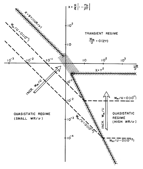
The resulting regimes of relative motion are displayed graphically in
Figure 5.8. The transient regime in
the upper right-hand sector of the graph is characterized
by large relative motion, as suggested by Equation 5.98.
The quasistatic regimes for WR/ν » 1 and
WR/ν « 1 are in the lower right- and left-hand sectors
respectively.
The shaded boundaries between these regimes are, of course,
approximate and are functions of the parameter Y, which must have
a value in the range 0<Y<1.
As one proceeds deeper into either of the
quasistatic regimes, the magnitude of the
relative velocity, WM/U, becomes smaller and smaller.
Thus, homogeneous flows (see Chapter 6) in which the
relative motion is neglected require that
either
X« Y2 or X « Y/(UR/ν).
Conversely, if either of these
conditions is violated, relative motion must be included in the analysis.
Figure 5.8
Schematic of the various regimes of relative
motion between a particle and the surrounding flow.
5.12 DEFORMATION DUE TO TRANSLATION
In the case of bubbles, drops, or deformable particles
it has thus far been tacitly assumed that
their shape is known and constant.
Since the fluid stresses due to translation may
deform such a particle, we must now consider not only the
parameters governing the deformation but also the consequences in
terms of the translation velocity and the shape.
We concentrate here on bubbles and drops in which surface
tension, S, acts as the force restraining deformation.
However, the reader will
realize that there would exist a similar analysis for deformable
elastic particles. Furthermore, the discussion will be limited to the case
of steady translation, caused by gravity, g.
Clearly the results could be extended to cover translation
due to fluid acceleration by using an effective value
of g as indicated in the last section.
The characteristic force maintaining the sphericity
of the bubble or drop is given by SR.
Deformation will occur when the characteristic anisotropy
in the fluid forces approaches SR; the magnitude of the anisotropic
fluid force will be given by
μW∞R for
W∞R/ν « 1 or by
ρW∞2R2 for
W∞R/ν » 1.
Thus defining a Weber number,
We=2ρW∞2R/S,
deformation will occur when We/Re approaches unity for
Re « 1 or when We approaches unity for Re » 1.
But evaluation of these parameters requires knowledge of the terminal velocity,
W∞, and this may also be a function of the shape.
Thus one must start by expanding the functional relation of
Equation 5.95
which determines W∞ to include the Weber number:
 | ......(5.101)
|
This relation determines W∞ where Fr
is given by Equation 5.93.
Since all three dimensionless coefficients in this functional
relation include both W∞ and R,
it is simpler to
rearrange the arguments by defining another
nondimensional parameter known as the
Haberman-Morton number, Hm, which is a
combination of We, Re, and Fr
but does not involve W∞.
The Haberman-Morton number is defined as
 | ......(5.102)
|
In the case of a bubble, mp « ρτ and therefore
the factor in parenthesis is usually omitted. Then
Hm becomes independent of the bubble size.
It follows that the terminal velocity of a bubble or
drop can be represented by functional relation
 | ......(5.103)
|
and we shall confine the following discussion to the nature of
this relation for bubbles (mp « ρτ).
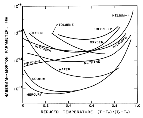
Figure 5.9
Values of the Haberman-Morton parameter, Hm,
for various pure substances as a function of reduced temperature.
Some values for the Haberman-Morton number
(with mp/ρτ=0)
for various saturated liquids are shown in Figure 5.9; other values
are listed in Table 5.3.
Note that for all but the most viscous liquids, Hm is much less than
unity.
It is, of course, possible to have fluid accelerations much larger
than g; however, this is unlikely to cause Hm values greater than
unity in practical multiphase flows of most liquids.
| TABLE 5.3
|
|
Values of the Haberman-Morton numbers, Hm=gμ4/ρS3,
|
|
for various liquids at normal temperatures.
|
|
|
|
Filtered Water | 0.25× 10⁻¹⁰ | Turpentine | 2.41× 10⁻⁹
|
|
Methyl Alcohol | 0.89× 10⁻¹⁰ | Olive Oil | 7.16× 10⁻³
|
|
Mineral Oil | 1.45× 10⁻² | Syrup | 0.92× 10⁶
|
Having introduced the Haberman-Morton number, we can now identify
the conditions for departure from sphericity.
For low Reynolds numbers (Re « 1) the
terminal velocity will be given by the equation
Re=C Fr2 where C is some constant.
Then the shape will deviate from spherical when We≥Re
or, using
Re=C Fr2 and
Hm=We3Fr-2Re-4, when
 | ......(5.104)
|
Thus if Hm<1 all bubbles for which Re « 1 will remain
spherical.
However, there are some unusual circumstances in which Hm>1 and
then there will be a range of Re, namely
Hm-½<Re<1,
in which significant departure from sphericity might occur.
For high Reynolds numbers (Re » 1)
the terminal velocity is given by
Fr≈O(1) and distortion will occur if We>1.
Using Fr=1 and
Hm=We3Fr-2Re-4 it follows that
departure from sphericity will occur when
 | ......(5.105)
|
Consequently, in the common circumstances in which
Hm<1, there exists a range of Reynolds numbers,
Re<Hm-¼, in which sphericity is maintained;
nonspherical shapes occur when Re>Hm-¼.
For Hm>1
departure from sphericity has already occurred at
Re<1 as discussed above.
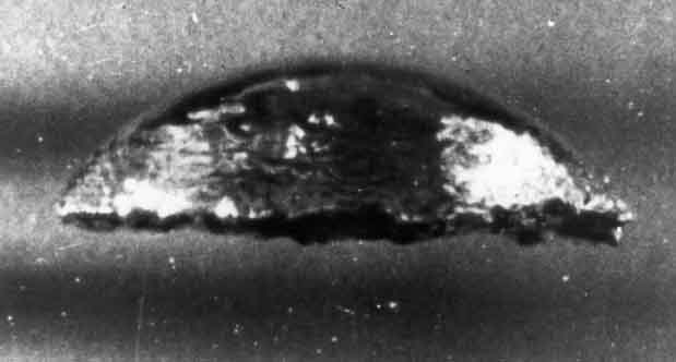
Figure 5.10
Photograph of a spherical cap bubble rising
in water (from Davenport, Bradshaw, and Richardson 1967).
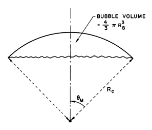
Figure 5.11
Notation used to describe the geometry of spherical cap bubbles.
Experimentally, it is observed that the initial departure
from sphericity causes ellipsoidal bubbles that may oscillate in
shape and have oscillatory trajectories (Hartunian and Sears 1957).
As the bubble size is further increased to the point at which
We≈20, the bubble acquires a new asymptotic shape, known as
a ``spherical-cap bubble.''
A photograph of a typical spherical-cap bubble is shown in Figure
5.10; the notation used to describe the approximate geometry of
these bubbles is sketched in figure 5.11.
Spherical-cap bubbles were first investigated by Davies
and Taylor (1950), who observed that the terminal velocity is simply
related to the radius of curvature of the cap, Rc,
or to the equivalent volumetric radius, RB, by
 | ......(5.106)
|
Assuming a typical laminar drag coefficient of CD=0.5,
a spherical solid particle with the same volume
would have a terminal velocity,
 | ......(5.107)
|
which is substantially higher than the spherical-cap bubble.
From Equation 5.106 it follows that the effective
CD for spherical cap bubbles is 2.67 based on the area
πR2B.
Wegener and Parlange (1973) have reviewed the literature on
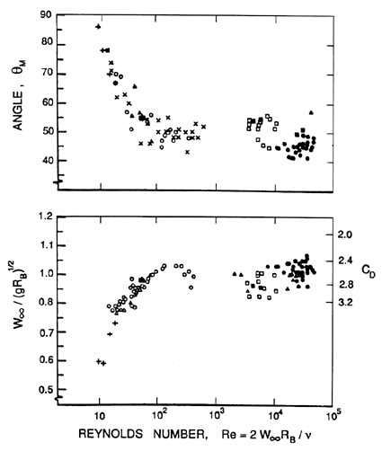
spherical cap bubbles. Figure 5.12 is taken from from their
review and shows that the value of
W∞/(gRB)½
reaches a value of about 1 at a
Reynolds number, Re=2W∞RB/ν, of about
200 and, thereafter,
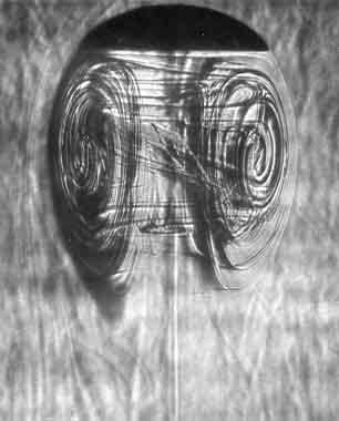
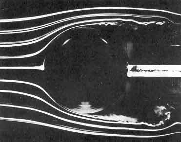
remains fairly constant. Visualization of the flow reveals that, for
Reynolds numbers less than about 360, the wake behind the bubble
is laminar and takes the form of a toroidal vortex
(similar to a Hill (1894) spherical vortex)
shown in the left-hand photograph of Figure 5.13. The wake undergoes
transition to turbulence about Re=360, and bubbles at higher Re
have turbulent wakes as illustrated in the right side of Figure 5.13.
We should add that scuba divers have long observed that spherical cap
bubbles rising in the ocean seem to have a maximum size of the order of
30cm in diameter. When they grow larger than this, they fission into
two (or more) bubbles. However, the author has found no quantitative
study of this fission process.
|
Figure 5.12
Data on the terminal velocity,
W∞/(gRB)½,
and the conical angle, θM ,
for spherical-cap bubbles studied by a number of different
investigators (adapted from Wegener and Parlange 1973).
Figure 5.13
Flow visualizations of spherical-cap
bubbles. On the left is a bubble with a laminar wake at Re≈180
(from Wegener and Parlange 1973) and, on the right, a bubble with a
turbulent wake at Re≈17000 (from Wegener, Sundell and
Parlange 1971, reproduced with permission of the authors).
In closing, we note that the
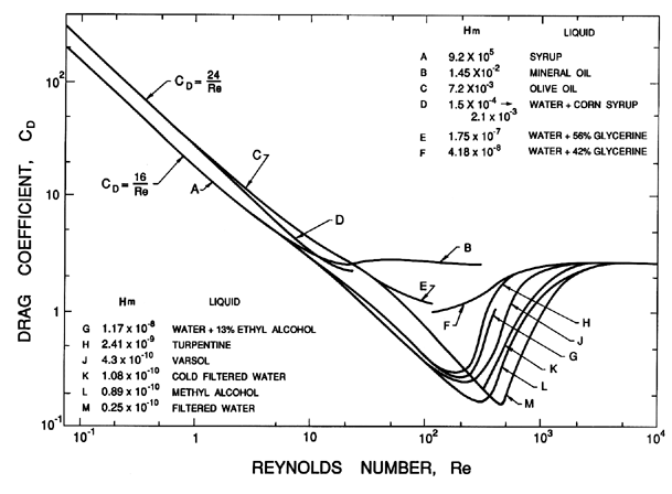
terminal velocities of the bubbles discussed here may be
represented according to the functional relation of Equations 5.103
as a family of CD(Re) curves for various Hm.
Figure 5.14 has been extracted from the experimental data of
Haberman and Morton (1953) and shows the
dependence of CD(Re)
on Hm at intermediate Re. The curves cover the spectrum from the low
Re spherical bubbles to the high Re spherical cap bubbles.
The data demonstrate that, at
higher values of Hm, the drag coefficient makes a relatively
smooth transition from the low Reynolds number result to
the spherical cap value of about 2.7. Lower values of Hm result in a
deep minimum in the drag coefficient around a Reynolds number of about
200.
Figure 5.14
Drag coefficients, CD, for bubbles as
a function of the Reynolds number, Re, for a range of
Haberman-Morton numbers, Hm, as shown. Data from Haberman and Morton
(1953).
REFERENCES
-
Basset, A.B. (1888). A treatise on hydrodynamics, II. Reprinted
by Dover, NY, 1961.
-
Batchelor, G.K. (1967). An introduction to fluid dynamics.
Cambridge Univ. Press.
-
Benjamin, T.B. and Ellis, A.T. (1966). The collapse of cavitation bubbles
and the pressures thereby produced against solid boundaries.
Phil. Trans. Roy. Soc., London, Ser. A, 260, 221--240.
-
Blake, J.R. and Gibson, D.C. (1987). Cavitation bubbles near boundaries.
Ann. Rev. Fluid Mech., 19, 99--124.
-
Brennen, C.E. (1982). A review of added mass and fluid inertial forces.
Naval Civil Eng. Lab., Port Hueneme, Calif., Report CR82.010.
-
Cole, R.H. (1948). Underwater explosions. Princeton Univ. Press
(reprinted by Dover, 1965).
-
Cunningham, E. (1910). On the velocity of steady fall of spherical particles
through fluid medium. Proc. Roy. Soc. A, 83, 357--365.
-
Davenport, W.G., Bradshaw, A.V., and Richardson, F.D. (1967).
Behavior of spherical-cap bubbles in liquid metals.
J. Iron Steel Inst., 205, 1034--1042.
-
Davies, C.N. (1966). Aerosol science. Academic Press, New York.
-
Davies, R.M. and Taylor, G.I. (1942). The vertical motion of a spherical
bubble and the pressure surrounding it. In
The Scientific Papers of G.I.Taylor, III, 320--336, edited by
G.K.Batchelor, Cambridge Univ. Press.
-
Davies, R.M. and Taylor, G.I. (1943). The motion and shape of the hollow
produced by an explosion in a liquid. In
The Scientific Papers of G.I.Taylor, III, 337--353, edited by
G.K.Batchelor, Cambridge Univ. Press.
-
Davies, R.M. and Taylor, G.I. (1950). The mechanics of large bubbles
rising through extended liquids and through liquids in tubes. Proc. Roy.
Soc. A, 200, 375--390.
-
Einstein, A. (1956). Investigations on the theory of Brownian movement.
Dover Publ., Inc., New York.
-
Green, H.L. and Lane, W.R. (1964). Particulate clouds: dusts, smokes
and mists. E. and F.N. Spon Ltd., London.
-
Haberman, W.L. and Morton, R.K. (1953). An experimental investigation of
the drag and shape of air bubbles rising in various liquids. David Taylor
Model Basin, Washington, Report No. 802.
-
Hadamard, J. (1911). Movement permanent lent d'une sphere liquide et
visqueuse dans un liquide visqueux.
Comptes Rendus, 152, 1735.
-
Harper, J.F., Moore, D.W. and Pearson, J.R.A. (1967). The effect
of the variation of surface tension with temperature on the motion of
bubbles and drops. J. Fluid Mech., 27, 361--366.
-
Hartunian, R.A. and Sears, W.R. (1957). On the instability of small
gas bubbles moving uniformly in various liquids. J. Fluid Mech.,
3, 27--47.
-
Herring, C. (1941). The theory of the pulsations of the gas bubbles
produced by an underwater explosion.
US Nat. Defence Res. Comm. Report.
-
Hill, M.J.M. (1894). On a spherical vortex.
Phil. Trans. Roy. Soc., London, Ser. A.,
185, 213--245.
-
Kaplun, S. and Lagerstrom, P.A. (1957). Asymptotic expansions of
Navier-Stokes solutions for small Reynolds numbers. J. Math. Mech.,
6, 585--593.
-
Kennard, E.M. (1967). Irrotational flow of frictionless fluid, mostly of
invariable density. David Taylor Model Basin, Washington,
Report No. 2299.
-
Keulegan, G.H. and Carpenter, L.H. (1958). Forces on cylinders and plates
in an oscillating fluid. U.S. Nat. Bur. Standards J. Res., 60,
No. 5, 423--440.
-
Klyachko, L.S. (1934). Heating and ventilation. USSR Journal Otopl.
i Ventil., No.4.
-
Lamb, H. (1932). Hydrodynamics. Cambridge Univ. Press.
-
Landau, L.E. and Lifshitz, E.M. (1959). Fluid Mechanics. Pergamon
Press, NY.
-
Moller, W. (1938). Experimentelle Untersuchungen zur Hydrodynamik der
Kugel. Physik. Z., 39, 57--80.
-
Morrison, F.A. and Stewart, M.B. (1976). Small bubble motion in an
accelerating liquid.
ASME J. Appl. Mech., 43, 399--403.
-
Morison, J.R., O'Brien, M.P., Johnson, J.W., and Schaaf, S.A. (1950). The
forces exerted by surface waves on piles. AIME Trans., Petroleum Branch,
189, 149--154.
-
Oseen, C.W. (1910). Über die Stokessche Formel und über die
verwandte
Aufgabe in der Hydrodynamik. Arkiv Mat., Astron. och Fysik,
6, No. 29.
-
Patton, K.T. (1965). Tables of hydrodynamic mass factors for
translational motion. ASME Paper, 65-WA/UNT-2.
-
Pearcey, T. and Hill, G.W. (1956). The accelerated motion of droplets and
bubbles. Australian J. of Phys., 9, 19--30.
-
Proudman, I. and Pearson, J.R.A. (1957). Expansions at small Reynolds
number for the flow past a sphere and a circular cylinder.
J. Fluid Mech., 2, 237--262.
-
Rudinger, G. (1969). Relaxation in gas-particle flow. In
Nonequilibrium flows. Part 1, (ed: P.P.Wegener), Marcel Dekker,
New York and London.
-
Rybzynski, W. (1911). Über die fortschreitende Bewegung einer
flüssigen Kugel in einem zähen Medium. Bull. Acad. Sci.
Cracovie, A, 40.
-
Sarpkaya, T. and Isaacson, M. (1981). Mechanics of wave forces on
offshore structures. Van Nostrand Reinhold Co., NY.
-
Stokes, G.G. (1851). On the effect of the internal friction of fluids on
the motion of pendulums. Trans. Camb. Phil. Soc., 9, Part II,
8--106.
-
Symington, W.A. (1978). Analytical studies of steady and non-steady
motion of a bubbly liquid. Ph.D. Thesis, Calif. Inst. of
Tech.
-
Taneda, S. (1956). Studies on wake vortices (III). Experimental investigation
of the wake behind a sphere at low Reynolds number.
Rep. Res. Inst. Appl. Mech., Kyushu Univ., 4,
99--105.
-
Torobin, L.B. and Gauvin, W.H. (1959). Fundamental aspects of solids-gas
flow. Part II. The sphere wake in steady laminar fluids. Canadian
J. Chem. Eng., 37, 167--176.
-
Wegener, P.P., Sundell, R.E., and Parlange, J.-Y. (1971). Spherical-cap
bubbles rising in liquids. Z. Flugwissenschaften, 19, 347--352.
-
Wegener, P.P. and Parlange, J.-Y. (1973). Spherical-cap bubbles.
Ann. Rev. Fluid Mech., 5, 79--100.
-
Yih, C.-S. (1969). Fluid mechanics. McGraw-Hill Book Co.
-
Young, N.O., Goldstein, J.S., and Block, M.J. (1959). The motion of
bubbles in a vertical temperature gradient.
J. Fluid Mech., 6, 350--356.
Back to table of contents
Last updated 12/1/00.
Christopher E. Brennen




 (s)
and
 (r,s):


 1(s,t)
far from the particle be equal to
 (s) is

 1(s) is


 is a dummy time variable.
This result must then be written in the original
coordinate framework with W=V-U and
can be generalized to the noncolinear case by
superposition so that


 ,
,
 ),
with origin at the center
of the image bubble. Assuming inviscid, irrotational flow,
Herring (1941) and Davies and Taylor (1943) constructed
the velocity potential, φ, near the bubble by considering an expansion
in terms of R/h where h is the distance of the bubble center from the
boundary. Neglecting all terms that are of order
R3/h3 or higher,
the velocity potential can be obtained by superposing the individual
contributions from the bubble source/sink, the image source/sink, the
bubble translation dipole, the image dipole, and one correction factor
described below. This combination yields

